Motion Control Devices
Motion control devices allow the user to control the physical position of objects from within fluxTrainer. There are various types of motion control devices supported by fluxTrainer:
Y axis: a single axis that moves a sample in a direction perpendicular to the line of the HSI camera. Alternatively the axis may also move the camera instead of the sample.
A Y axis is used for composing a full HSI cube with just a line camera. The camera sees different lines while the axis is in motion. Those lines can be concatenated to obtain an image.
Z axis: a single axis that controls the distance between the camera and the sample.
A Z axis is used for ensuring that the camera correctly focusses on the sample.
Pan/Tilt unit: a rotational device that allows the user to move in two dimensions: panning and tilting. The camera is mounted to the unit and follows the motion.
A pan/tilt unit is useful for scanning the sky with a HSI camera.
XY table: a table that can move in two directions; one along the line that the camera sees, and the other perpendicular to it. The table may be used to scan samples that are wider than the line of the line camera. This may be the case if the camera is connected to a microscope optic.
XY table with integrated Z axis: an XY table that also has an integrated Z axis. fluxTrainer will treat such devices as if there were two separate motion control devices (one for the XY table, the other for the Z axis).
Connecting To Devices
Most motion control devices are connected via a serial port to the computer. This means that they are not automatically detected by fluxTrainer. Instead the corresponding drivers always appear in the device list, allowing the user to select the serial port the device is connected to. Instead of selecting a serial port the user can also select Automatic to indicate that the driver should try to find the device behind every serial port of the computer.
Reference Runs
To make use of motion control devices, fluxTrainer must be able to obtain the absolute position of the device, as well as the size of the motion range the device supports.
In many cases this can be obtained by first performing a so-called reference run. Each axis is first moved to one end until a limit switch is triggered. Then each axis is moved to the other end until another limit switch is triggered. fluxTrainer now knows the size of the motion range, as well as the current absolute position of the axis.
When a motion control device is connected to fluxTrainer, if it supports reference runs, fluxTrainer will automatically perfrom a reference run when a device is connected.
Some devices support remembering the current absolute position and motion ranges while they are powered on. In that case, if fluxTrainer detects that a reference run was already performed for a motion control device, it will not perform a reference run again during connect.
As long as there is no slippage in the motor, all motion control devices will be able to remember their current absolute position while connected to fluxTrainer.
It is possible to redo a reference run from within fluxTrainer if that is required, for example because the motor has slipped. This is discussed in the following sections.
Since a reference run is performed automatically after connecting to a device, if a device is not referenced, one of the following situations will have occurred:
The device does not support reference runs.
The user has aborted the last reference run of the device.
An error occurred during the reference run of the device.
Aborting Reference Runs
Reference runs can be aborted by the user. A reference run may be aborted by one of the following methods:
Click the Stop all motion button in the device settings.
Click the Stop button in the Motion Control window.
Click the Abort button in the Linear Motion Control dock widget. (If applicable.)
Click the Abort button in the 2D recording widget. (If applicable.)
After aborting a reference run it the motion control device will not be properly referenced. In that case the user has the option to perform the reference run again to be able to fully utilize it. Some devices may still support relative movements of the device from the Motion Control window in the unreferenced state, other devices may not.
Special Device Actions
Motion control devices have special actions that are shown above their parameters:
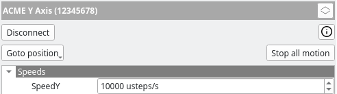
There are one or two additional buttons available.
Stop all motion
This button is always present and allows the user to stop all motion of the device immediately.
Goto position
Some devices may have hard-coded special positions. The Goto position button will open a menu with all currently available special positions:
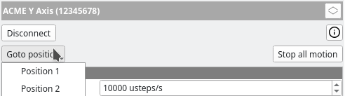
A special position could be a loading position where it is easy to load/unload a sample in the given measurement setup. It could also be a position where an integrated white reference material is placed directly beneath the HSI camera line in order for the user to properly measure a white reference. There are multiple options, and the driver of the motion control device will provide those to the user.
If the driver does not support special positions, the Goto position button will not be shown.
Pan/Tilt Units
For Pan/Tilt units there is also an additional drop-down shown here that the user can use to select which axis to use as the recording direction:
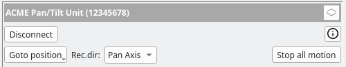
This is described in further detail in the Pan/Tilt Units section.
Motion Control Window
The Motion Control window can be used to directly control motion control devices connected to fluxTrainer. It can be accessed via the View menu: select View, and then Motion Control…
Alternatively, click the ![]() button in
the calibration view to open the window.
button in
the calibration view to open the window.
If no motion control device is connected the window will look like this:
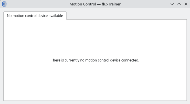
Once a motion control device is connected, the contents of the window changes.
The data acquisition window can still be interacted with while the motion control window is open.
Y Axis Devices
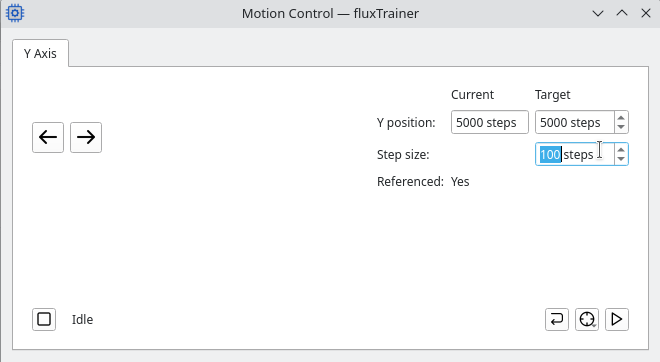
When a Y axis device is connected, the motion control window provides the user with various control options:
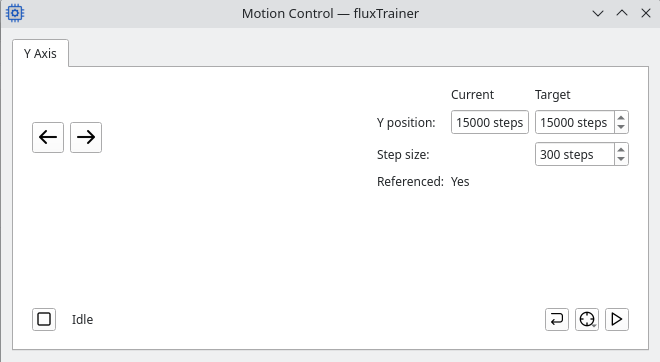
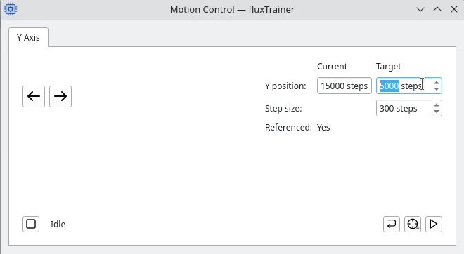
On the right side towards the top the current position is shown. Next
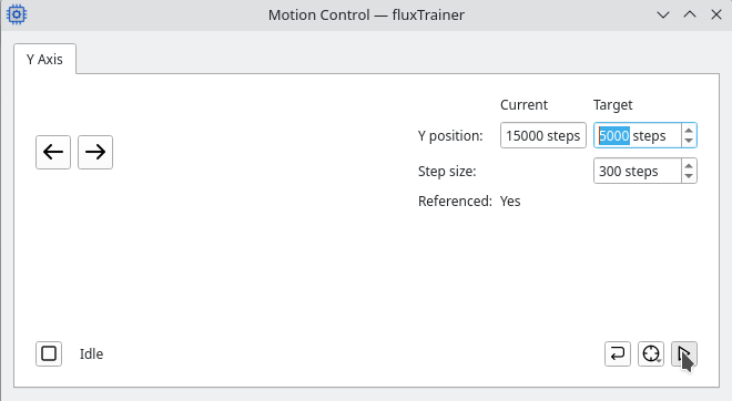
to that the user can enter a target position to go to. Clicking the
begin movement button, ![]() , fluxTrainer will move the
motion control device to the chosen target position:
, fluxTrainer will move the
motion control device to the chosen target position:
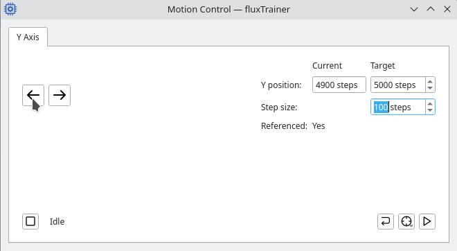
Alternatively the user can configure a step size and use the two
large movement buttons at the left side of the window
(![]() ,
, ![]() ) to move the axis by the
configured step size:
) to move the axis by the
configured step size:

Below the step size the window shows whether the motion control device is currently referenced. If a device is not referenced, some drivers still allow the user to perform relative movements of the device in an unreferenced state, while others do not.
Finally there are various buttons at the bottom:
Stop: stops all current motion of the device
Redo reference run: performas a new reference run for the deivce
Goto special position: opens the special position menu and allows the user to select a new special position to move to. (This is identical to the functionality in the device list.)
Move: begins movement towards the specified target position (see above)
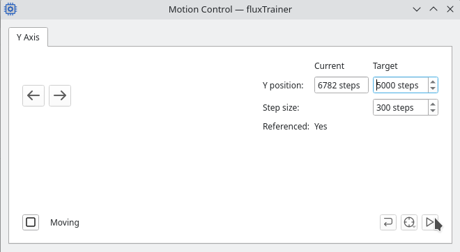
While the device is in motion the window is disabled except for the
stop, ![]() , button. The current status of the motion control
device is found next to that button.
, button. The current status of the motion control
device is found next to that button.
Z Axis Devices
When a Z axis device is connected, the motion control window will show the following options:
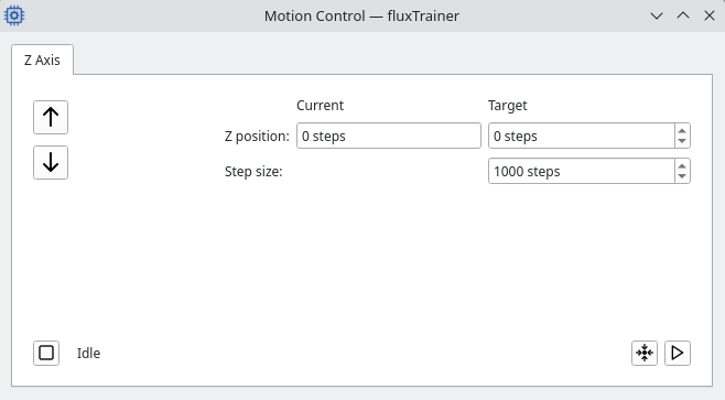
Z axis devices are not referenced, and allow for relative movement. On the right side the current position of the device relative to an arbitrary zero position is shown. (Typically the current position will be 0 after connecting to the device initially.)
The user can enter an absolute position in the Target Z position
edit field, and then press the ![]() Move button to
move to that position. (If the device reaches a limit switch, motion
will stop at that point.)
Move button to
move to that position. (If the device reaches a limit switch, motion
will stop at that point.)
The ![]() Reset zero to current position button will
reset the zero position of the Z axis to the current position.
Reset zero to current position button will
reset the zero position of the Z axis to the current position.
Alternatively the user can select a step size in the Step size edit
field, and use the ![]() Up and
Up and ![]() Down
buttons to move the Z axis relatively by the indicated step size.
Down
buttons to move the Z axis relatively by the indicated step size.
As with Y axis devices, in the lower left there is the ![]() Stop button that stops all current motion of the device. Next to it
the current status of the device is shown.
Stop button that stops all current motion of the device. Next to it
the current status of the device is shown.
XY Tables
When an XY table is connected, the motion control window will show the following options:
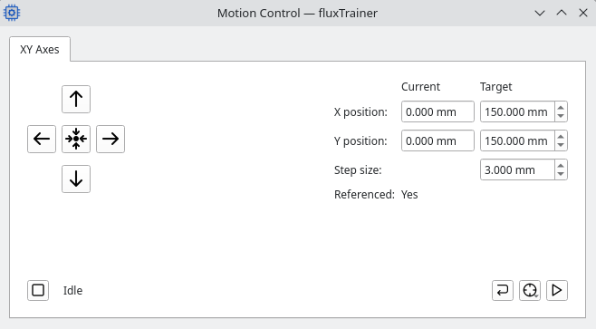
On the right the user can see the current position in both the X and Y
coordinates. They can also set a target position and use the
![]() Move button to move to that position.
Move button to move to that position.
The Step Size that can be set below the current position is used for
moving in both X and Y directions with the ![]() Up,
Up,
![]() Right,
Right, ![]() Down, and
Down, and
![]() Left buttons.
Left buttons.
Use the ![]() Move to center button to move to the
center of the 2D table.
Move to center button to move to the
center of the 2D table.
As with the other types of motion control devices, at the bottom left
there is the ![]() Stop button to stop all motion. Next to it
the current status of the XY table is displayed.
Stop button to stop all motion. Next to it
the current status of the XY table is displayed.
On the bottom right there are three buttons:
Pan/Tilt Units
When a Pan/Tilt unit is connected, the motion control window will show the following options:
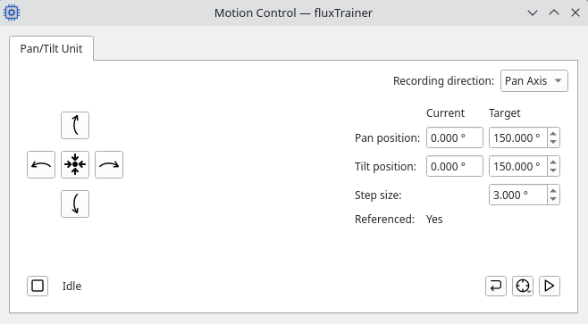
At the top right the user can select the recording direction to use for this unit. This is described in further detail in the Pan/Tilt Units section.
Below that the current pan and tilt positions are shown. The user can
also enter a new target position and use the ![]() Move
button to move to that position.
Move
button to move to that position.
The step size of the unit can be set below that. Using the
![]() Pan Left,
Pan Left, ![]() Pan Right,
Pan Right,
![]() Tilt Up, and
Tilt Up, and ![]() Tilt Down buttons
the unit will move that specified step size in the chosen direction.
Tilt Down buttons
the unit will move that specified step size in the chosen direction.
The ![]() Goto center button on the left moves the
pan/tilt unit to the center of its range of motion.
Goto center button on the left moves the
pan/tilt unit to the center of its range of motion.
At the very bottom left the ![]() Stop button stops all motion.
Next to it the current status of the device is shown.
Stop button stops all motion.
Next to it the current status of the device is shown.
At the bottom right there are three buttons:
Z-Axis Motion Control Devices
Z axis devices are there to change the distance of the camera to the sample that is being measured. This allows the user to adjust the focus of the camera in the measurement setup without having to phsyically change the setup.
A Z axis can only be moved from the Motion Control window. The basic calibration and/or recording logic do not interact with the Z axis directly.
Typically a user will open the Motion Control window while in the Calibration view, move the window to the side so that the raw camera data is clearly visible, and then adjust the Z position of the setup until the desired focus is achieved.
Y-Axis Motion Control Devices
fluxTrainer supports Y axis motion control devices to move the sample relative to the line camera to build up a HSI cube line by line. The motion of the Y axis is then tied to the user beginning and ending recordings, as well as using the player.
Linear Motion Control Dock Widget
When connected to a Y axis motion control device, the Linear Motion Control dock widget will appear. If the dock widget is accidentally closed, it can be reopened from the View menu.
If the axis is currently not referenced (due to the user aborting the reference run, or an error during a reference run), the dock widget will instead appear like this:
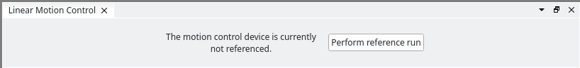
Click on the Perform reference run button to restart the reference run.
While a reference run is active, the dock widget will look like this:
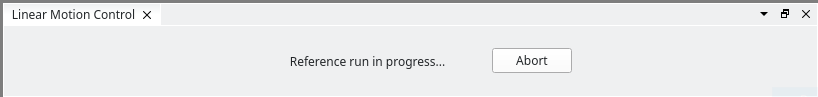
Here the Abort button aborts the current reference run.
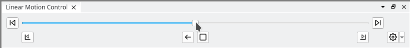
When the axis are referenced, the dock widget will appear as follows:
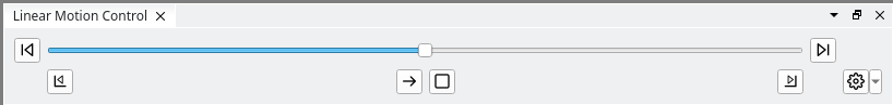
The top row consists of the following elements:
The button
Go to lower limit… that initiates movement to the lower limit of the device.
If a soft limit has been set (see below) and the current position is above the soft limit, it will move to the soft limit instead of the physical limit of the device.
A slider which indicates the current position of the axis.
The button
Go to upper limit… that initiates movement to the upper limit of the device.
If a soft limit has been set (see below) and the current position is below the soft limit, it will move to the soft limit instead of the physical limit of the device.
The bottom row consists of the following buttons:
The button
Set lower limit that sets or removes a soft limit for the travel of the device (see below).
A button with a left
or right
arrow that indicates the next direction of travel of the device. Clicking the button will reverse the direction of travel.
This direction is used whenever the Recording or Player functionality wants to start motion automatically, without the user explicitly choosing a movement direction. In that case the direction selected here will be used, and the device will move in that direction until the limit is reached.
When a soft or hard limit is reached, this direction will automatically change.
The stop button
The button
Set upper limit that sets or removes a soft limit for the travel of the device (see below).
The button
that opens a menu with advanced options. Currently the user can choose to redo the reference run of the device from here.
Moving the device
The user can drag the slider with the mouse to manually initiate motion for the device. As soon as the device is in motion, the target of the motion will be highlighted with a red bar, and the slider position will change to the current position during the motion.
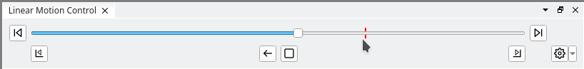
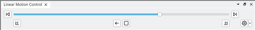
Once the device has reached the target position, the red bar disappears again:
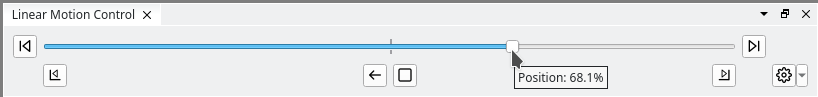
The user can also click on any position at the bar with the right mouse button to open a context menu:
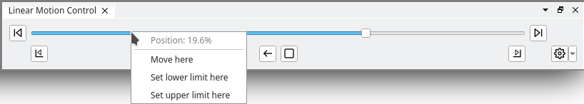
The context menu will display the current position (as a percentage of the distance, taken from the lower limit). It also has an entry Move here to tell fluxTrainer to move the device to that specific position.
Soft Limits
It is also possible to set soft limits for the device. These limits will apply whenever fluxTrainer is asked to move to the end of the range - instead of moving to the physical end of the device.
This is used to define the actual range of motion for measurement purposes. Most axis devices will cover a range that is larger than required to actually move the sample underneath the camera. This feature allows the user to limit the motion range to actual range required to perform the measurements.
When lower and/or upper limits are set, fluxTrainer will indicate these with brackets along the slider:
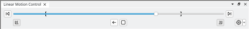
Clicking on the Go to lower limit or Go to upper limit buttons will now stop at the limits the user has set.
To set a limit, there are two options:
Right-click on the axis and select Set lower limit here or Set upper limit here. This will set the lower or upper limit to the position the user has clicked on (without the device having to have moved to that position first).
Move to the desired position of the limit and click the Set lower limit or Set upper limit button. The corresponding limit will be set to the current position.
If a limit is set, the corresponding Set lower limit and Set upper limit button will be depressed (see the previous screenshot) to indicate that a limit is present.
Click one of the limit buttons while it is depressed and it will release, removing the soft limit.
Once the user has moved to a soft limit (or beyond a limit), the next travel direction button will automatically point in the opposite direction. For example, if the user moves to the lower limit or beyond it, the next travel direction will point towards the upper limit, and vice-versa.
Motion Sync Settings Area
If both a motion control Y axis device as well as a camera is connected to fluxTrainer, a new settings box Motion Sync will appear below the motion control device:
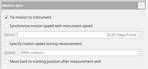
Here the user can alter various settings that influence how a Y axis motion control device interacts with the Recording and Player functionalities.
If the current settings are stored in a Profile, the current motion sync settings will also be saved there.
Tie motion to instrument
If this checkbox is not set, the Y axis motion control device is completely independent of the current measurement state. The user can start a recording independently of the motion control device.
If this checkbox is set (default), starting a recording and/or starting the player will also begin movement. It will travel in the direction the button for the next travel direction shows, until a limit (soft or hard) has been reached. And once the motion control device has reached that limit, the recording (or the player) is automatically stopped at that point.
All other options specified here are only applicable if this checkbox is set.
Synchronize motion speed with instrument speed
This setting can be used to set a constant factor between the frame rate of the camera and the motion speed. Changing the frame rate of the camera (even implicitly through the exposure time) will cause fluxTrainer to automatically use a different movement speed.
This speed setting only applies when using the Recording or Player functionalities. In that case, before the device begins its movement, the speed is first updated to the calculated speed. Then, after the device has stopped again, the speed of the device is changed back to the value it had previously to starting the recording.
Note
For this setting to be useable the camera must provide fluxTrainer with sufficient information about the time between two frames.
Specify motion speed during measurement
This setting is mutually exclusive with the Synchronize motion speed with instrument speed setting. Here, instead of specifying a factor relative to the frame time of the camera, the user can specify a speed explicitly.
As with the other setting, this speed setting only applies when using the Recording or Player functionalities. In that case, before the device begins its movement, the speed is first updated to the speed specified here. Then, after the device has stopped again, the speed is changed back to the value it had previously to starting the recording.
This setting is useful for using a different speed for performing the recordings and moving around manually with the slider. To achieve this configure the desired manual movement speed in the settings of motion control device, and then configure the speed for recordings here.
Move back to starting position after measurement end
If this option is set, whenever a recording is performed (or the player is used), once the device has reached its target position, the device will move back to the position it started the motion from. The speed used to move back is the speed that would be used if the user manually moves the device around, and not the recording speed.
This setting is useful for measurement setups that require repeated measurements.
Influence on Recording
If the user has selected to tie motion to instrument in the Motion Sync settings, the following behavior will happen:
When the user presses the Record button in the Recording tab, the Y axis is automatically started. If the user has specified a different recording speed in the Motion Sync settings, that speed is used for the movement. The device will move to the next limit in the currently selected direction of travel. (The second button in the lower row of the Linear Motion Control dock widget.)
Once the limit has been reached, the recording will be stopped automatically. The motion control device’s speed will be reset to the value set before the recording started, if applicable. The next recording direction button will now point back in the other direction.
Note
If the motion control device was already in motion when the user pressed the record button, the behavior will be as if the user hadn’t selected tie motion to instrument at all.
Influence on Player
The Player will react very similar to the Recording functionality when a Y axis is present. When the user starts the player, the Y axis will automatically begin movement, and once the limit has been reached, the player will automatically stop. As with the Recording functionality, speeds are adjusted as needed. Finally, if the axis is already moving when the user starts the player, the Y axis will have no effect on the player, as if the tie motion to instrument checkbox in the Motion Sync settings had not been set.
However, there is one additional option that the user can configure in the settings: if the user chooses to auto-restart the player once a limit has been reached, the player will move back and forth between the limits until the user explicitly stops it.
Pan/Tilt Motion Control Devices
Pan/Tilt devices provide the user with the option to rotate around two axes (pan and tilt). In the Motion Control window both axes can be manipulated to move the device into the desired position.
To use a pan/tilt unit the user must first select the recording direction. This is the axis that fluxTrainer will interact with.
By default the Pan axis is the recording direction of a pan/tilt unit. If that is chosen the Tilt axis can only be manipulated from within the Motion Control window. But fluxTrainer interacts with the Pan axis as if it were a regular Y axis. (The same Linear Motion Control dock widget is shown, for example.)
It is also possible to switch to the Tilt axis as the recording direction; in that case fluxTrainer will treat the Tilt axis of the pan/tilt unit as if it were a Y axis, and the Pan axis can only be interacted with in the Motion Control window.
The selection of the recording direction can happen in two places:
In the device settings below the Disconnect button.
In the Motion Control window at the top right of the pan/tilt settings.
Which axis should be used as the recording direction will depend on how the line camera is mounted to the pan/tilt unit.
XY Motion Control Devices
XY tables are motion control devices that allow the user to move two perpendicular axes independently from each other, that either the sample or the camera can be moved to any position within a defined rectangle.
Connecting to an XY table has two consequences:
The Player is be available.
The Recording tab switches into the 2D Recording mode that deals specifically with XY tables.
See the section on 2D Recording for further details on how to use XY tables from fluxTrainer.