2D Recording
When both a XY motion control device and a camera are connected, fluxTrainer will switch modes. The Player will not be available, and instead of the Recording tab there will be a 2D Recording tab instead.
Instead of continuously recording data, in this mode recordings are done step by step: First, fluxTrainer will determine the set of positions it needs to record data from. Then it will move the XY table to each position individually, and while the XY table has stopped at that position, record one or more frames. It will then proceed to the next position, until it has completed the recording.
This mode allows for the user to perform very precise and repeatable recordings, and also allows the user to record samples that are wider than the field of view of the line scan camera. Since the XY table is used for precise positioning of each frame, the individual lines can be arranged together to a much larger image/cube.
Requirements
For the 2D recording mode to work with fluxTrainer, there are two requirements:
First there needs to be an XY table connected to fluxTrainer that provides a high positioning accuracy, and provides fluxTrainer with physical length units for its position, for example millimeters.
Second the user must have properly set up the Pixel Size (x) calibration setting so that fluxTrainer knows how large a camera frame is physically.
Settings
When both a camera and an XY table are connected to fluxTrainer, a new settings box will appear:
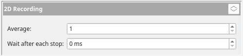
These settings influence the behavior of the 2D recording functionality.
Average
This setting controls how many frames should be averaged at each
position while making the recording. By default this setting will
be 1 (no average). Increasing this value will reduce the amount
of noise in each measurement, but will also increase the time it
takes to perform the measurement in question.
Wait after each stop
Some XY tables still vibrate a bit after stopping. This will often only be on the order of microns, but with a very precise measurement setup, measuring a frame immediately after each stop may cause the frame to include motion blur from the vibration. This setting allows the user to configure a wait time to use after each new position has been reached, so that vibrations can subside before the frames are being measured.
Increasing this value will also increase the time it takes to perform the measurement in question.
View Area
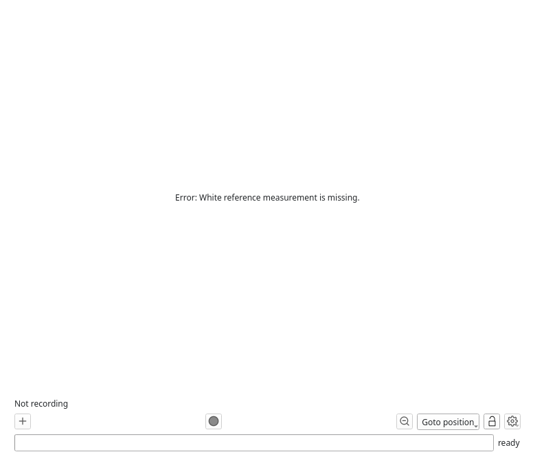
After initially switching to the 2D Recording tab, if the user has not yet measured a white reference, or not yet set up the physical pixel size, an error message will be shown:
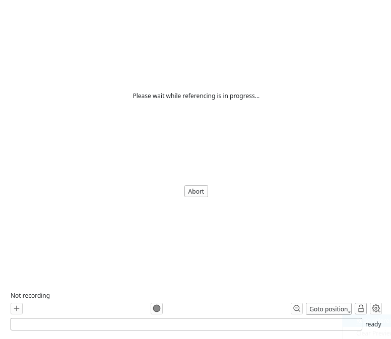
If instead the reference run of the XY table is still in progress, that will be indicated to the user:
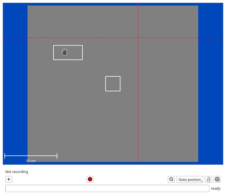
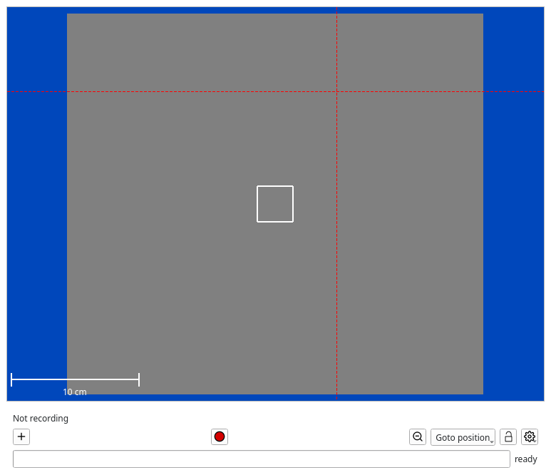
However, once the reference run has successfully completed, the user will see a screen that looks similar to the following:
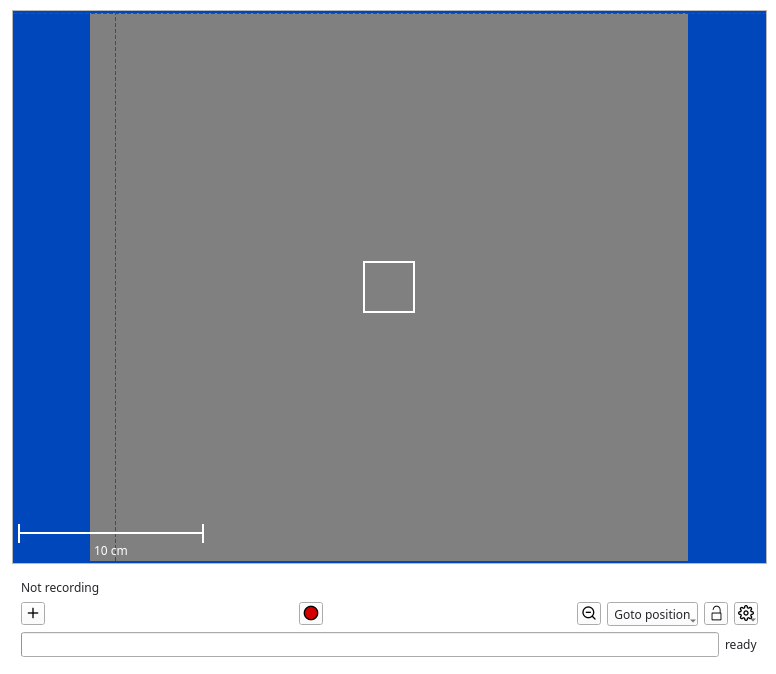
The dark gray is the entire measurement area, defined by the limits of the XY table. A scale is provided to the user for convenience.
The current position of the camera is shown with a dark red dashed crosshair.
Note
Since the table moves the sample, and the crosshair shows which part of the sample the camera is currently looking at, the movement of the table is reversed relative to the movement shown on screen.
For example, if the camera is looking at the top-left corner of the sample, the table will be in the bottom-right corner of its movement range.
In the middle of the screen there is a white rectangle. This is a defined measurement area. By default a measurement area is created that is in the center of the movement range, as wide as the line of the camera, and has square proportions.
Click in any free space in the gray area with the right mouse to open a context menu:
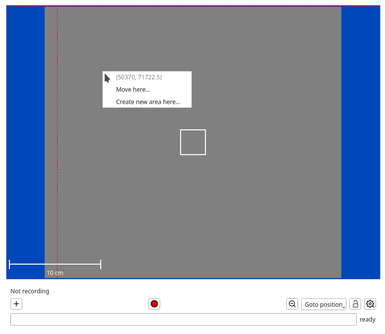
It will show the current position where the user has clicked, and provide two actions:
Move here will move the table to that position.
Create new area here… will create a new measurement area at that position (see below)
Using the Move here action the user can move the device to an arbitrary position they selected.
Below the preview area there is a button bar with the following buttons:
The
Add new area button adds a new recording area to the screen.
The
Record button begins the recording process. During recordings it will change to a
Stop button that aborts the recording process.
The
Reset Zoom button resets the zoom of the 2D recording area view.
The Goto position button allows the user to go to a special position provided by the driver. (This is the same functionality that has been discussed in the Motion Control section.)
The
Lock recording areas button can be used to lock the current recording areas and prevent accidental manipulation by the user. (It will change to
button to indicate this.)
The
Advanced actions button will open a menu that allows the user to perform various advanced actions (see below)
Recording Areas
There are two methods to define a new area: either click the
![]() button at the bottom, or use the context
menu and select the Create new area here… option.
button at the bottom, or use the context
menu and select the Create new area here… option.
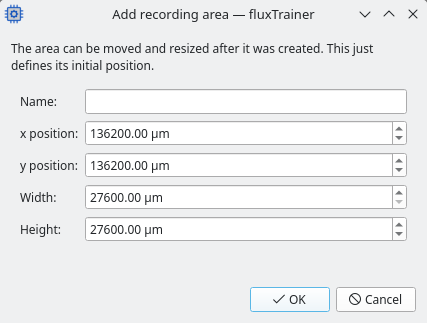
In this window the user must specify a name for the recording area, as well as specify the position, width and height of the area.
The width and height of the area are always multiples of the size of each camera line. For example, if a pixel has a size of 30 micrometers, and the camera line has a width of 1024 pixels, then every area must have a width that is a multiple of 30720 micrometers (30 * 1024), and a height that is a multiple of 30 micrometers (a line has a height of 1 pixel).
The position can be adjusted according to the precision of the motion control device.
The position of the area is the position of the top-left corner of the area.
When clicking on the ![]() button, it will use
the position and size of the default area as the default settings for
this window. When using the context menu the position of the mouse
click will be used for the position of the new area.
button, it will use
the position and size of the default area as the default settings for
this window. When using the context menu the position of the mouse
click will be used for the position of the new area.
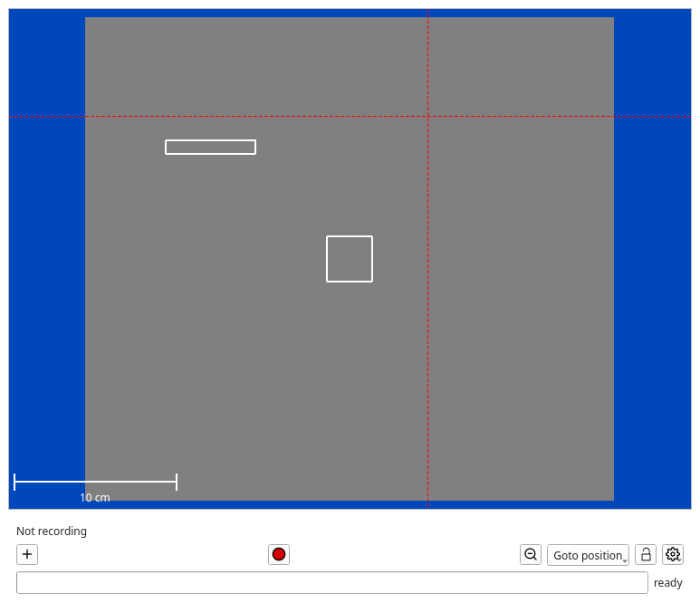
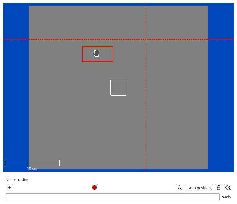
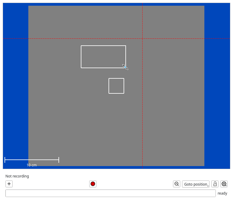
Once the user has defined a new area, it will appear in the preview screen as a new rectangle:
Editing area parameters
To edit the area parameters, right-click withing the defined area to open the context menu.
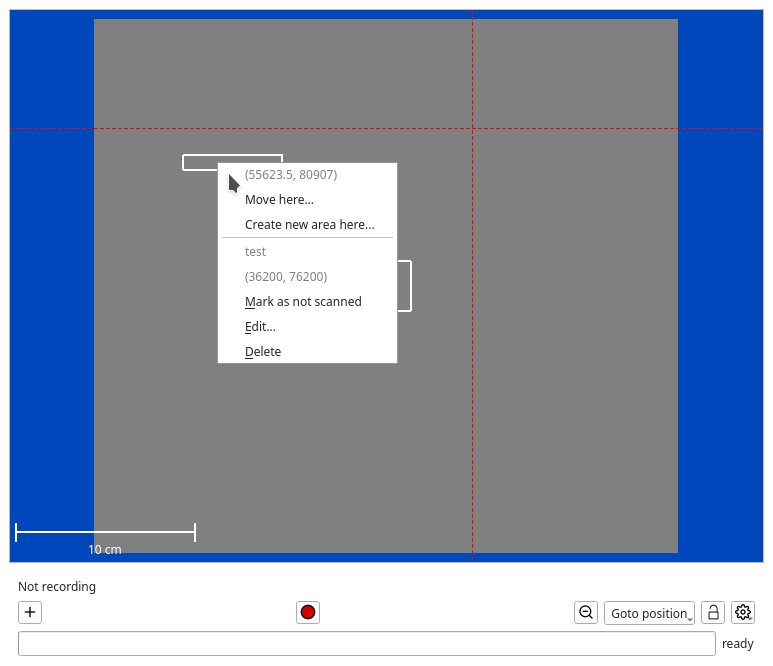
In addition to the menu options that are displayed when outside of an area, additional options appear that are only available when inside of an area. The position of the top-left corner of the area is also shown.
The option Edit will open the window again where the name, position, and size of the area can be fine-tuned.
Moving an area
To move an area, it is also possible to drag it with the mouse. Press the left mouse button while within the area, and drag the mouse to the new position while keeping the left mouse button pressed. Release the left mouse button and the area will have moved to the new position.

When moving an area close to the boundary of the measurement range, the area will always remain inside the measurement range.
Since accidentally moving an area can happen easily, it is possible to
lock the current scan areas with the ![]() Lock scan areas button to prevent this. The button then changes to
Lock scan areas button to prevent this. The button then changes to
![]() to indicate that areas cannot be edited.
to indicate that areas cannot be edited.
Resizing an area
An area can be resized by pressing the left mouse button while the mouse is above the outline of the area, and then dragging the mouse until the desired size has been reached. After releasing the left mouse button, the area will have the new size.
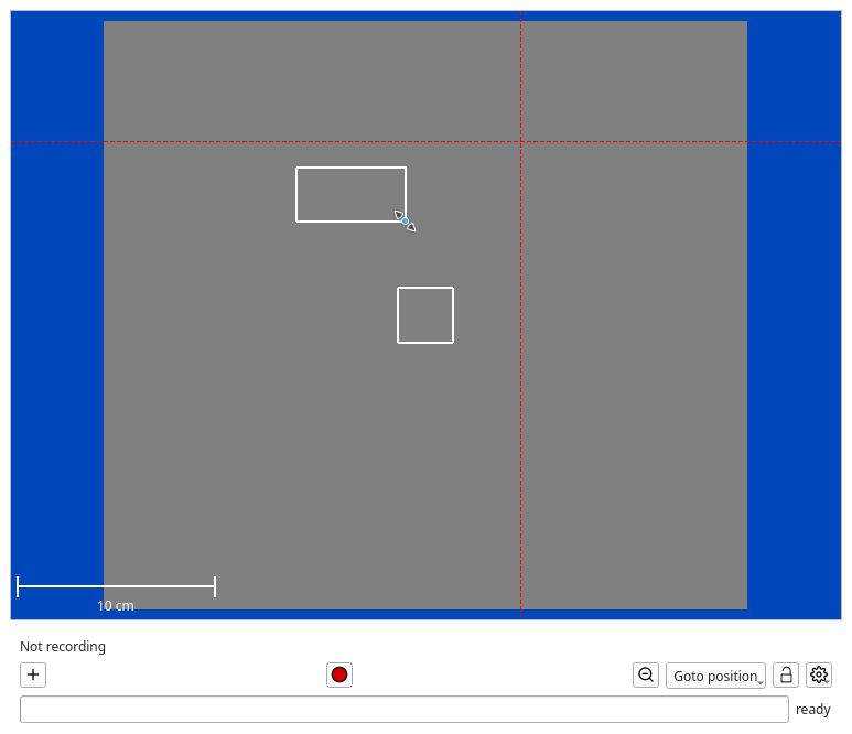
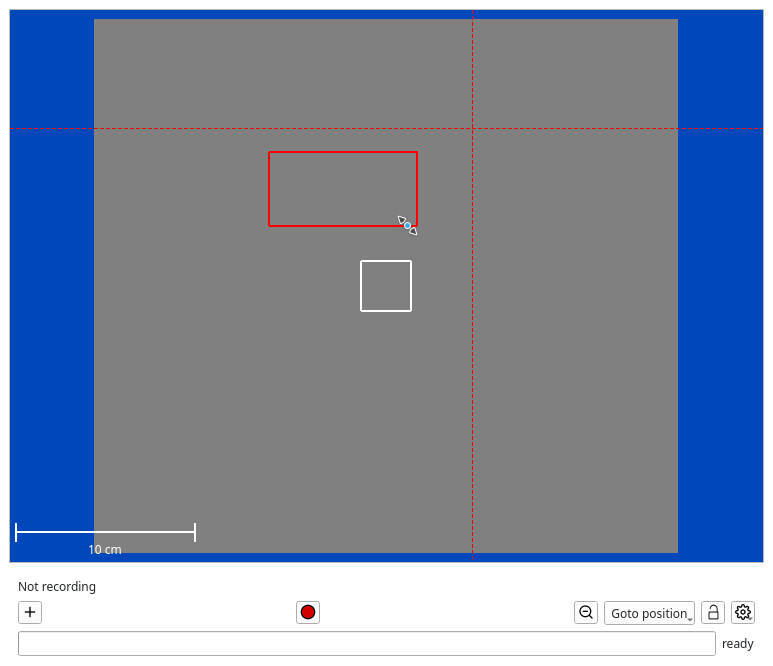
Since the width and height of the area have to be set in discrete increments, the resizing process will snap while moving the mouse to the increments specified by the user.
As it is easy to accidentally resize an area, it is possible to lock
the current scan areas with the ![]() Lock scan areas button to prevent this. The button then changes to
Lock scan areas button to prevent this. The button then changes to
![]() to indicate that areas cannot be edited.
to indicate that areas cannot be edited.
Deleting an area
To delete an area, right-click within the area, and use the Delete menu item to delete it. After affirming a prompt that the are should be deleted, it will be removed from the screen:
Marking an area as not scanned
Once an area has been recorded completely, it is marked as scanned. If multiple areas are defined, only areas that have not yet been marked as scanned will be scanned when a recording is made. To ensure that a recording will also include a previously scanned area, the area can be marked as not scanned this this menu item in the context menu of the area.
The exception to this rule is that if all areas have been marked as scanned and the user clicks on the record button, the user will be given the opportunity to scan all areas again regardless.
Default Area
The default area is constructed in the following manner:
Its width is the width of a single line of the HSI camera.
Its height is chosen to be the same as its width.
Its position is chosen so that it is centered in the measurement area.
Its name will be
Recording.
Interaction With Profiles
If the user saves the current device settings in a profile, the following settings pertaining to the 2D recording logic will also be saved:
The number of frames to average per position (can be configured in the 2D Recording settings box in the device settings list)
The wait time after each stop (can be configured in the 2D Recording settings box in the device settings list)
Whether the user has
Performing Recordings
Clicking on the ![]() Record button will begin recording.
fluxTrainer will go through all defined areas. It will move the XY
table to each position that is required. After a position is reached
one or more frames are acquired at that position. fluxTrainer will
then proceed to the next position, and repeat that process until all
positions in all areas have been recorded.
Record button will begin recording.
fluxTrainer will go through all defined areas. It will move the XY
table to each position that is required. After a position is reached
one or more frames are acquired at that position. fluxTrainer will
then proceed to the next position, and repeat that process until all
positions in all areas have been recorded.
The number of frames that are taken at each position can be configured in the 2D Recording settings box.
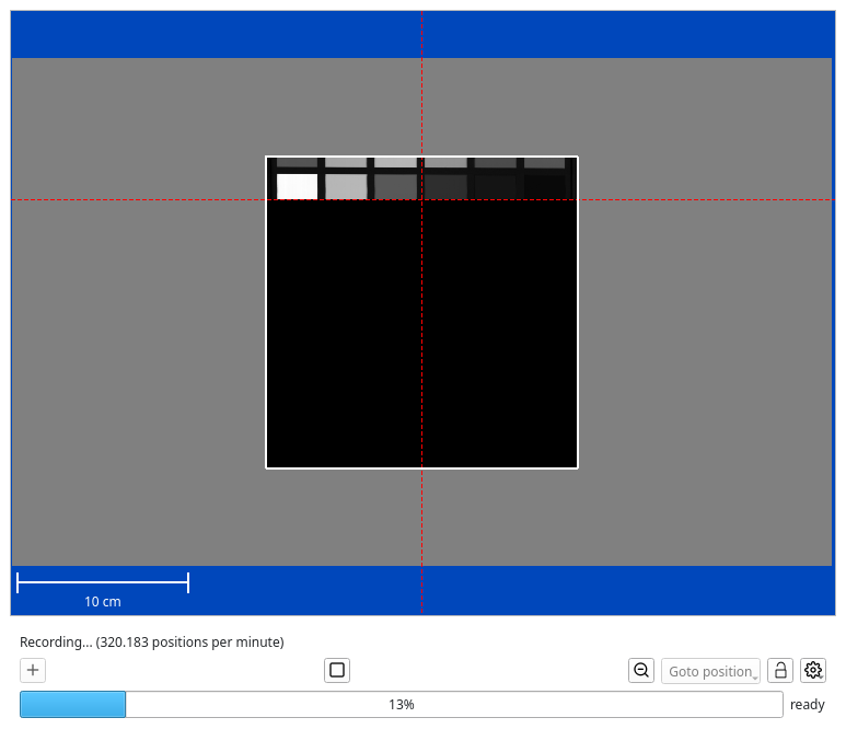
While the recording is being made fluxTrainer will gradually generate a preview for the recording. The preview image shown for each area will have a lower resolution during the recording process of that area. Once that area has been fully recorded, the preview image will be replaced by the image that was recorded in that area.
The following screenshot shows the middle of such a recording process:
After the recording has completed the screen may look like this:
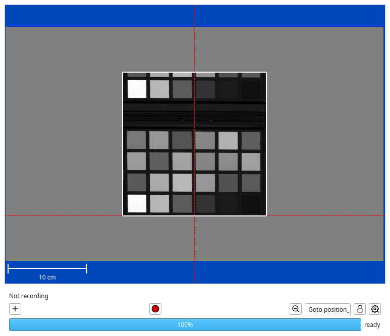
The recording will then be available in the recording manager for the user to save.
Note
In contrast to the normal recording mode, recordings made in the 2D recording mode will always be in reflectances if the user has selected reflectances as the recording mode in the calibration view. It is not possible to store recordings as raw intensities with separate references in this mode.
The recording will be available in the recording manager for the user to save and/or import into fluxTrainer. Each area will be a separate recording. Instead of the date the default name of each recording will be the name of the area that was defined by the user.
Warning
It is easily possible to define a recording area that is so large that is cannot be loaded back into memory in fluxTrainer. Since during the recording process the file is only written out piece by piece (while the recording takes place), fluxTrainer is very unlikely to exhaust the RAM of the system during the recording process itself. But when loading a HSI cube into fluxTrainer directly, the cube must fit into memory.
Advanced Actions
Clicking on the ![]() Advanced Actions button in the lower
right corner will open a menu that shows the actions the user may
take:
Advanced Actions button in the lower
right corner will open a menu that shows the actions the user may
take:
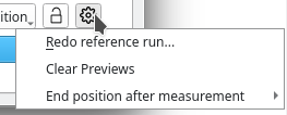
Redo reference run
Selecting Redo reference run will redo the reference run. This is equivalent to the user clicking the corresponding button in the Motion Control window.
Clear Previews
The Clear Previews item will clear all existing previews.
End position after measurement
The End position after measurement item will open a sub-menu that lists all special positions available by the driver. These are the same positions that are also available with the Goto position button. It also contains an entry (None), which is the default.
If the default (None) is selected, then once the last area has been scanned, fluxTrainer will leave the table at the last position that was measured.
If any other entry is selected, fluxTrainer will initiate a move to that position after the last area has been scanned. This is a useful setting if the table has a specific load/unload position where a sample can be loaded. In that case the user can load the sample, start the measurement with this option on, leave the system running until the measurement has completed. Once the user returns the system will be back in that position, but a recording will have been made.