First Steps
By clicking on the Connect Device tab in fluxTrainer, a new window will open that allows the user to connect devices:
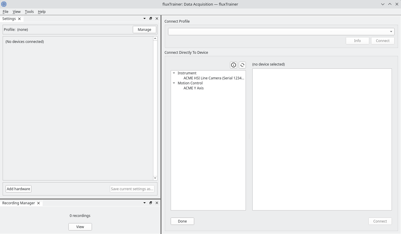
On the left side there are two dock widgets: Settings and Recording Manager.
On the right side by default there is the Connect Device view that allows the user to select a device to connect to.
Connecting to a device
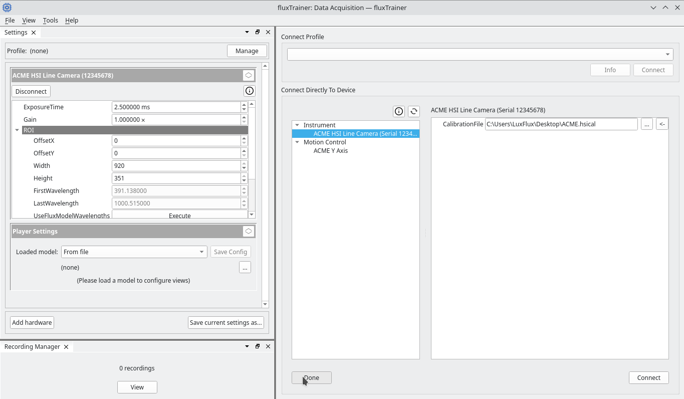
The left part of the Connect Directly To Device area contains a list of devices that have been detected. In this case we will connect to the ACME HSI Line Camera device. First, select the device in the list:
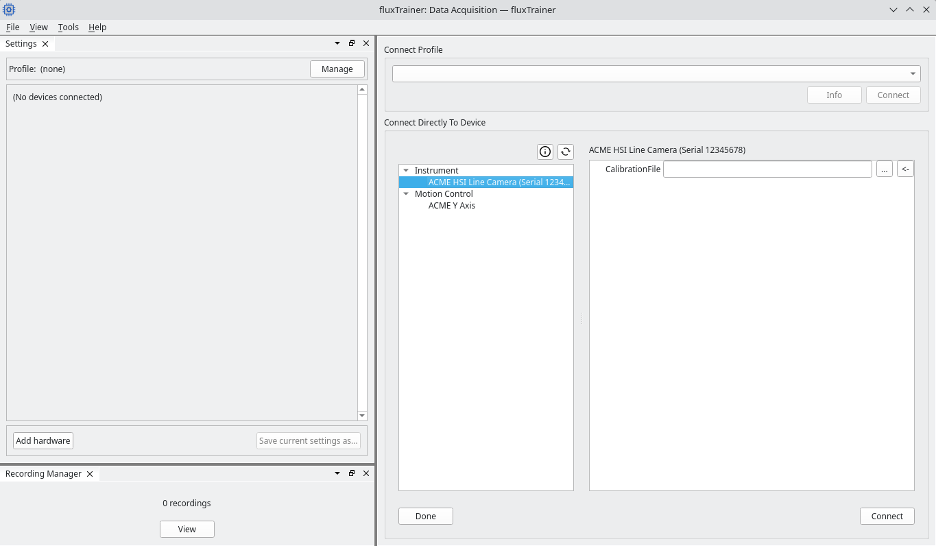
On the right hand side a list of parameters will appear. These parameters will influence how the device is being connected. Which parameters appear will depend on the specific device.
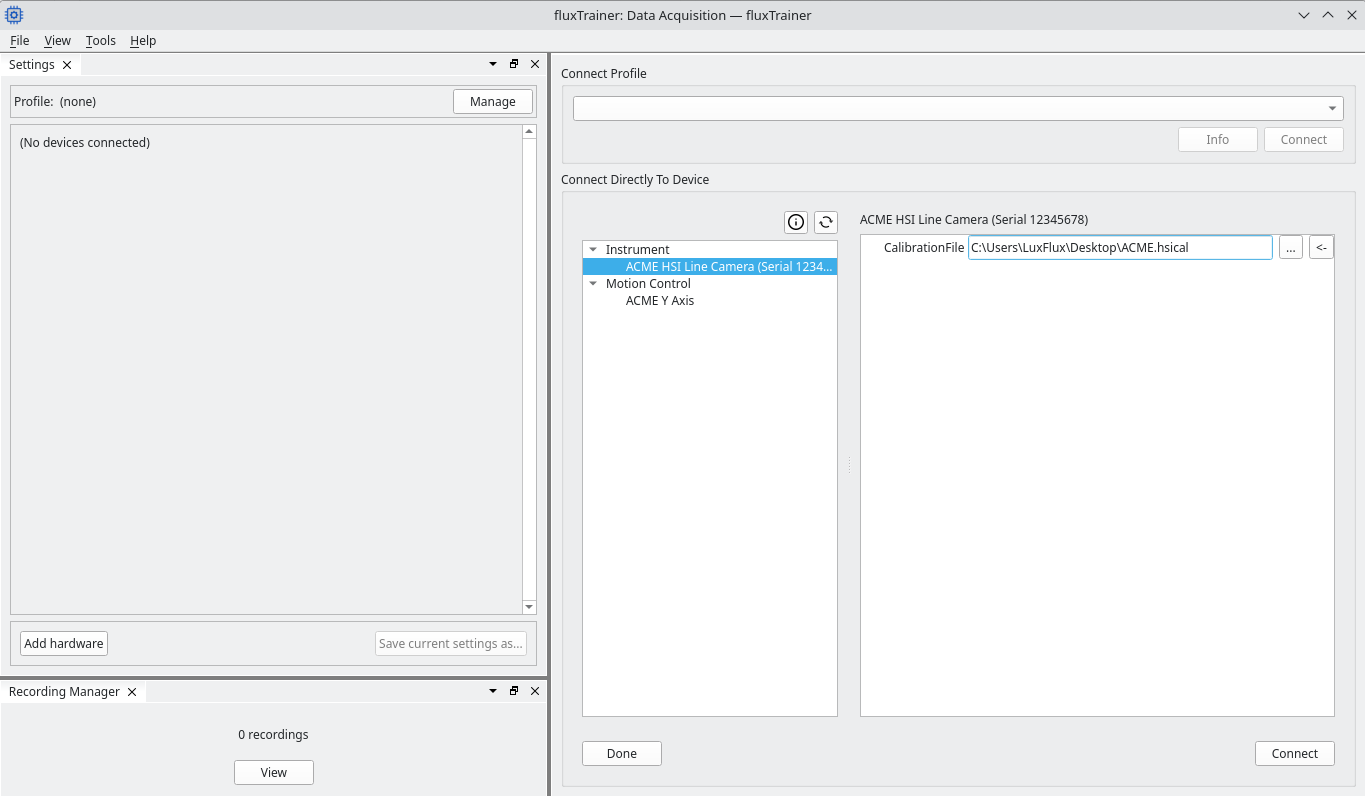
Many cameras will require the user to provide a calibration file. Click on the … button to open a file chooser that allows the user to select the appropriate calibration file. After selecting the file, the file’s path is now displayed in the settings:
Now the user may click the Connect button in the bottom right corner. This will begin the camera connection process. During the connection process a new block will appear in the Settings dock widget:
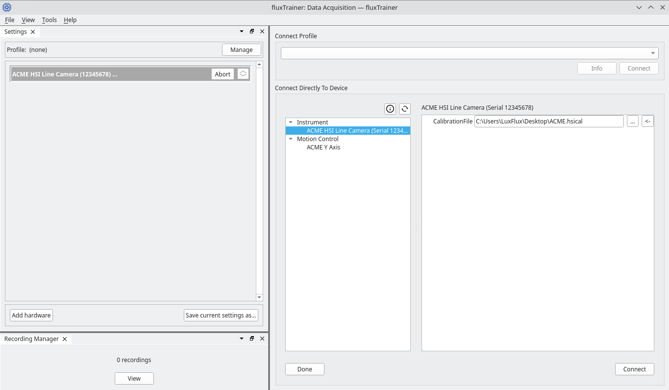
It contains an Abort button to allow the user to abort the connection process if desired.
Once the connection process has completed, the block in the Settings dock widget will expand and contain a list of settings of the camera:

Which settings appear on the left side will depend on the specific device that is being connected. Most cameras will typically have similar settings though.
After the device has connected press the Done button in the lower left corner of the main area to tell fluxTrainer that no further devices should be connected at this stage:
This will now switch to the instrument view that may be used to perform calibration measurements, record data, and apply a model to data that is being recorded live.
Calibration Measurements
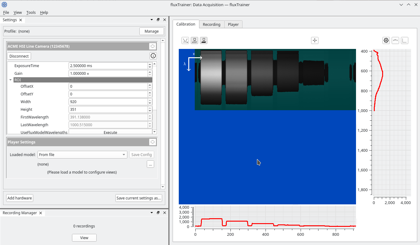
Once a camera is connected, acquisition will be started by default. The calibration view shows the raw frame of the camera’s sensor. For a HSI line camera (pushbroom) this means that it will show a two-dimensional image, with one of the axes being the the spatial direction, and the other being the spectral direction:
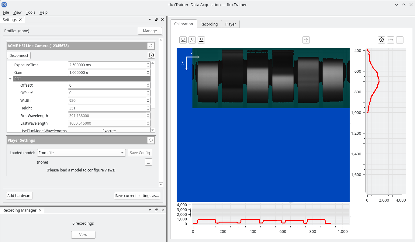
In this example the y dimension of the image is the spectral direction, while the x dimension is the spatial direction. This is common for HSI cameras, but there are some that are configured differently. fluxTrainer will show two axis arrows with the corresponding labels in the image to indicate which direction is the spatial direction (x), and which direction is the spectral direction (λ).
Above the image there are multiple buttons that allow the user to perform measurements, register calibration settings, or switch the desired recording mode.
Below and to the side of the image there are chart views present. These charts show the average intensity of the current frame that is being displayed as the image. In this case the chart to the right hand side shows the average spectrum across all spatial pixels. The chart on the bottom shows the intensity of the line averaged over all spectral bands. This is useful when changing the focus of the lense to ensure that the resulting image is sharp.
Under and Overexposure
The view will display the raw data in form of a grayscale image, with higher intensities corresponding to higher raw sensor values. However, it also provides indications for under- and overexposure. The scaling of the color map corresponds to the input range of the sennsor.
If the raw data of a specific pixel is exactly 0, that pixel will be shown in a dark blue. (A different shade of blue than the background of the view.) This means that no light was encountered by that specific pixel.
If the value of a specific pixel is within the lower 5 percent of the total value range, it’s color is given by what the grayscale color of that pixel would be, but shaded in teal.
If the value of a specific pixel is exactly the maximum value, i.e. the device has entered saturation, that pixel will have the color red.
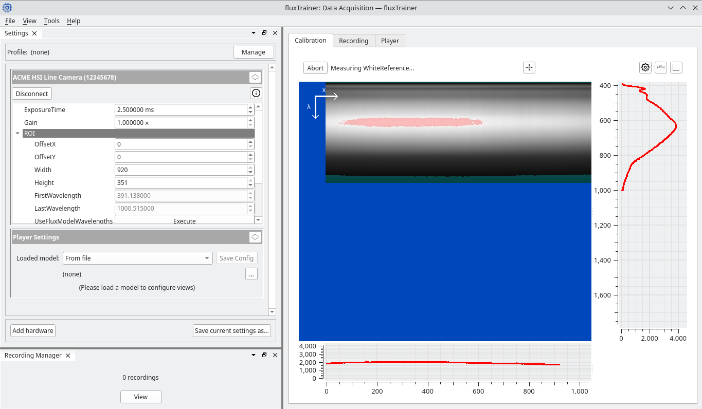
If the value of a specific pixel is within the upper 5 percent of the total value range, it’s color is given by what the grayscale color of that pixel would be, but shaded in pink.
In general saturation should always be avoided, i.e. pixels should never be red in order for the measurement to work properly.
Changing Exposure Time and Gain
Most cameras have settings for exposure time and gain. The exposure time determines how long light is allowed to interact with the sensor pixels (i.e. how long they are exposed). Gain is a value that influences the readout of the sensor pixels.
Setting a larger exposure time and/or larger gain will result in larger measured values. A larger exposure time will also likely decrease the amount of frames that can be captured in a time interval (as a single frame’s exposure takes longer), while a larger gain will result in more detector noise.
The user can specify these parameters in the Settings dock widget on the left side of the window. After entering a new value in the settings widget, press Enter. fluxTrainer will then tell the camera to use that value and the image in the calibration area should immediately change accordingly.
Measure a white reference
To perform a white reference measurement first ensure that a proper white reference material is positioned below the camera so that the entire camera image is filled with it.
Ensure that the exposure time and/or gain are set appropriately so that no saturation occurs, but are also large enough. (The white reference is likely the brightest object that will be measured by the camera, so the intensity of the white reference should ideally be scaled so that some pixels are already shaded pink (to indicate they are in the upper 5 percent of the total value range), but no pixel is red.
Afterwards click on the ![]() white reference
measurement button. This will start the white reference meausrement:
white reference
measurement button. This will start the white reference meausrement:
Once the white refereence measurement has completed, the previous screen returns, but the white reference button is now pressed in. This indicates that a white reference measurement is currently present.
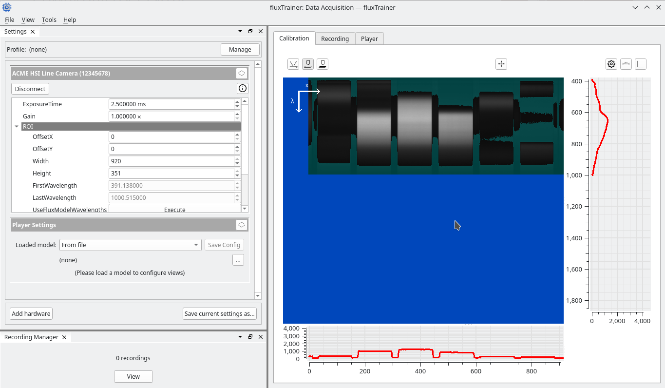
Warning
If the button is clicked again while it is pressed in, fluxTrainer will forget the previously measured white reference.
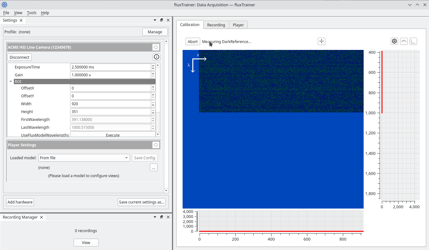
Measuring a dark reference
To reduce the effect of camera noise it is recommended to also measure a dark reference. Some cameras have a built-in shutter that will automatically close when a dark reference is measured. Others do not. In that case it is recommended to screw the lens cap onto the lens to block all light entering the camera before measuring the dark reference.
After the view of the camera is completely blocked (and the image has
gone dark), press the ![]() dark reference measurement
button. This will start the dark reference measurement:
dark reference measurement
button. This will start the dark reference measurement:
Once that is complete the dark reference button will now also be pressed in to indicate that a dark reference has been measured:
Changing parameters after reference measurements
When changing parameters such as exposure time, gain, or region of interest, the previously measured white and dark references will not fit the current camera settings anymore. fluxTrainer will detect this and automatically remove the previously measured references.
The user would then have to measure the white and dark references again.
HSI Cube Recording
Now that both white and dark references have been measured, the user may switch to the Recording tab (towards the top of the window). For line cameras this will enable a waterfall view of lines that are being acquired by the camera. The waterfall will always display an average over all spectral bands.
If no motion is happening, the line camera will always record the same line.
However, if the user moves the object below the camera at a constant speed, each line that is measured by the camera will contribute to the reconstruction of the image of the object underneath:
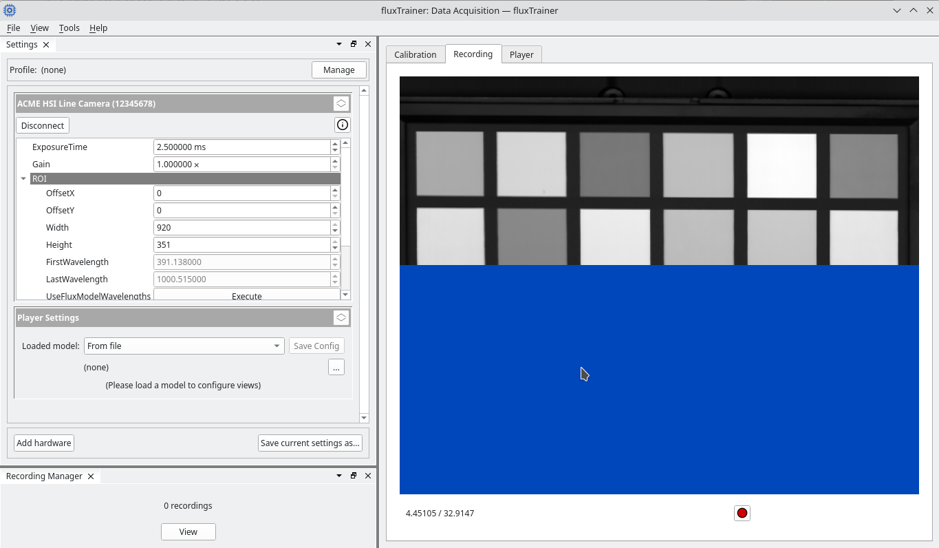
The user may then press the ![]() record button to begin
recording. fluxTrainer will mark the beginning of the recording with
an orange indicator:
record button to begin
recording. fluxTrainer will mark the beginning of the recording with
an orange indicator:
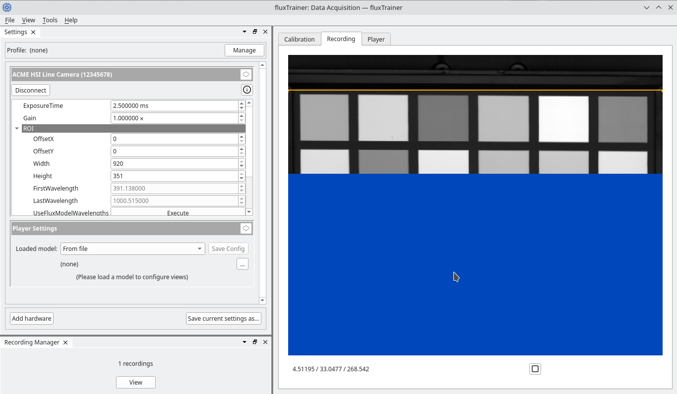
Clicking on the ![]() stop button will end the recording at
the current position. fluxTrainer will also add a marker to the
waterfall where the recording stopped:
stop button will end the recording at
the current position. fluxTrainer will also add a marker to the
waterfall where the recording stopped:
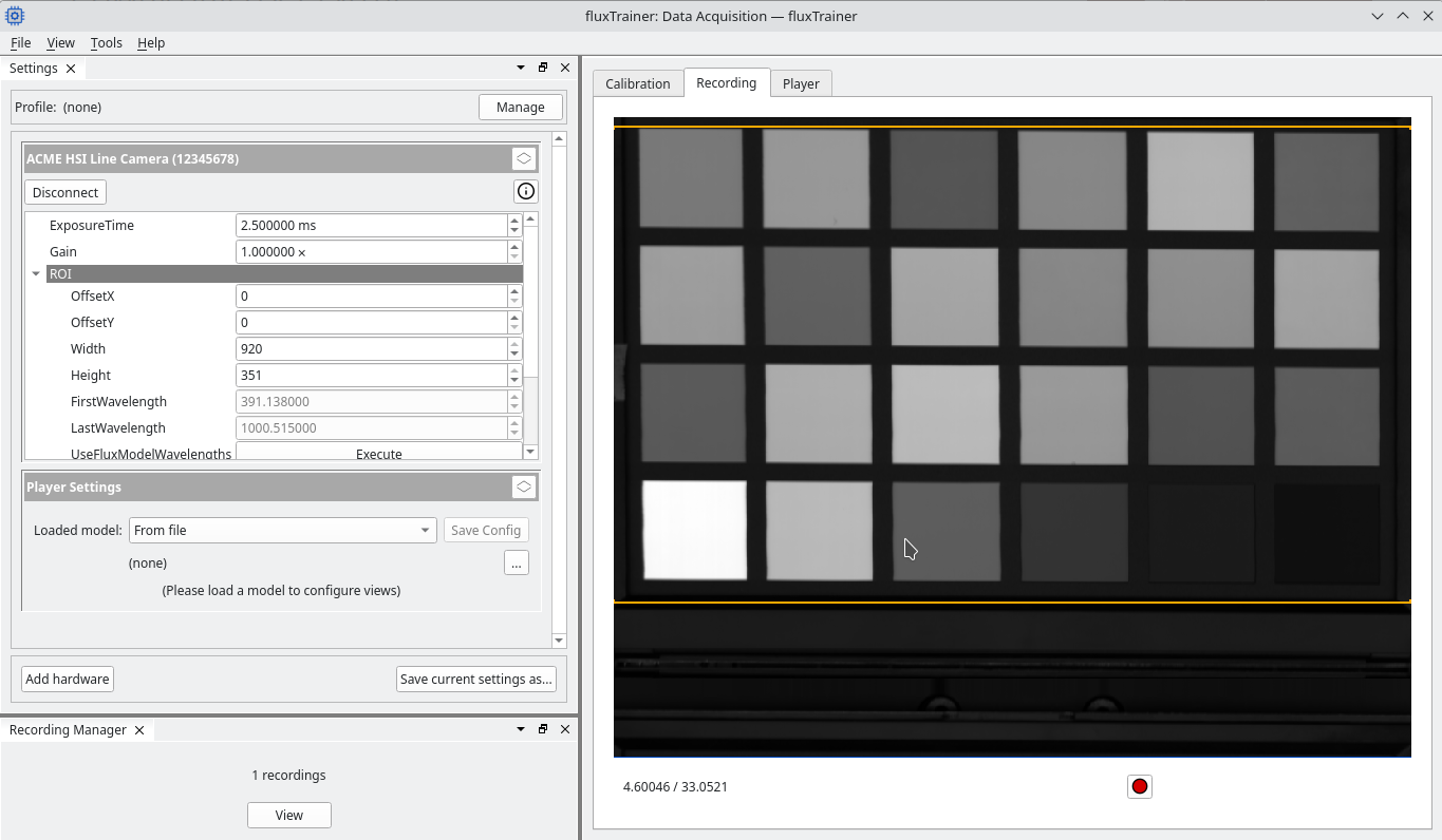
In the lower left Recording Manager dock widget there is now an indicator that a recording has been made. Clicking on the View button will open a new window that displays the recordings:
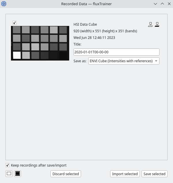
The window contains a list of all recordings (in this case one). Each recording has a checkbox to select/unselect the recording, a preview image, some metadata of the recording, a field for the name of the recording, and a drop-down to select the format the recording should be stored as.
In this case we want to call the recording ColorChart1, so
we change the title accordingly:
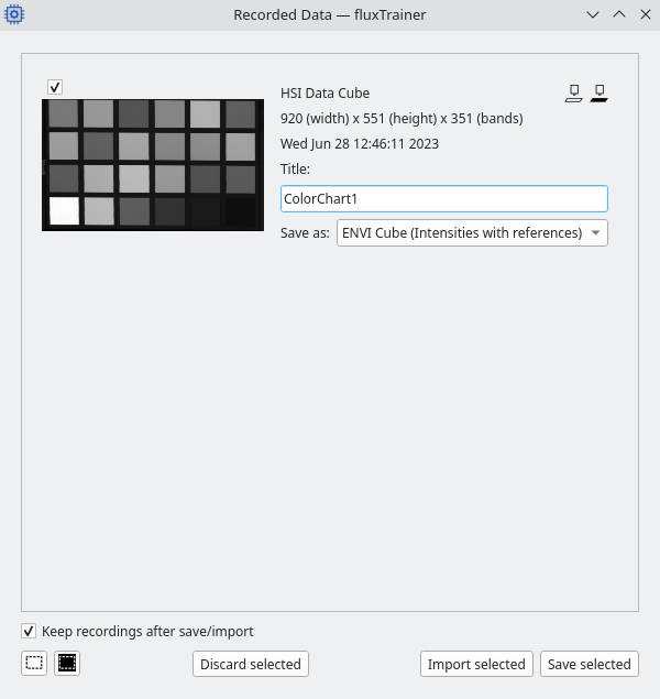
Clicking the Save selected button (bottom right) will export all selected recordings in the chosen output format. When clicking the button the user will be asked for a directory to store all recordings in. The names of the recordings will be used as their file names.
After a recording has been exported in this manner it will be removed from the list of available recordings. It can be imported into the data viewer if required.
Alternatively there is also the Import selected button, which will import all selected recordings as cubes of the current project in fluxTrainer. (The recordings are not saved as a file on disk in that case, and would only be saved if the user saved the current project.) After directly importing recordings they will also be removed from the list of available recordings.